Прочитайте отрывок из книги "Learning UML" (Unified Modeling Language), автор Sinan Si Alhir, и дайте русский эквивалент выделенных жирным шрифтом слов в приведённом контексте.
In the UML, an action state is shown as a shape with a straight top and bottom and
convex arcs on the two sides, and is labeled with the name of an operation or a
description of the processing. Figure 8-1 shows the various action states associated
with the project management system.

An initial action state indicates the first action state on an activity diagram. In the
UML, an initial action state is shown using a small solid filled circle. A final action
state indicates the last action state on an activity diagram. In the UML, a final action
state is shown using a circle surrounding a small solid filled circle (a bull’s eye).
Figure 8-2 updates Figure 8-1 with an initial and final action state. An activity diagram
may have only one initial action state, but may have any number of final action
states.

In the UML, a control-flow transition is shown as a solid line from a source action
state to a target action state. Figure 8-3 shows the order of action states associated
with the project management system.

In the UML, an object-flow transition is shown as a dashed arrow between an action
state and an object. An action state that uses an object as input is shown with the
object-flow transition arrow pointing from the object to the action state. An action
state that updates or produces an object as output is shown with the object-flow
transition arrow pointing from the action state to the object. Figure 8-4 shows the
objects used by the action states associated with the project management system.

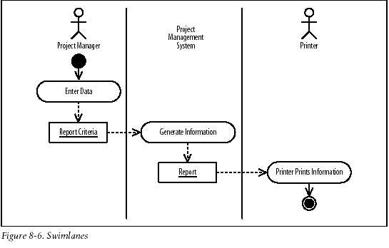
A swimlane is a visual region in an activity diagram that
indicates the element that has responsibility for action states within the region.
In the UML, a swimlane is shown as a visual region separated from neighboring
swimlanes by vertical solid lines on both sides and labeled at the top with the element
responsible for action states within the swimlane. Figure 8-6 shows the swimlanes
associated with the project management system.
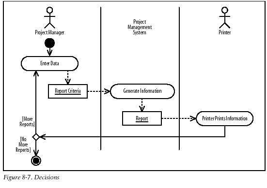
In the UML, a decision is shown as a diamond shape with incoming control-flow
transitions and outgoing control-flow transitions where each outgoing control-flow
transition is labeled with a guard condition in square brackets indicating the condition
that must be satisfied for the transition to fire, or occur. Figure 8-7 shows that
once a report is printed, a project manager may choose to print more reports. Notice
that because the diamond shape is in the project manager’s swimlane, the project
manager is responsible for making the decision.